Computer Aided Machine Drawing
|
1. Course Objectives: The objective of Computer Aided Drawing Lab (CAD) is to improve the efficiency, accuracy, and quality of the design process in various engineering and manufacturing fields. And also is to provide practical learning on various CAD tools are used to create, modify, analyse, and optimize designs of products and parts in industries like mechanical, civil, electrical, electronics. |
|
|
To understand the current scenario and apply knowledge of engineering, science, and mathematics for designing part components using computer-aided design (CAD) packages, typically follow a structured approach that integrates the principles of engineering design with the capabilities of modern software tools. To mould students to become a professional with all necessary skills and sound knowledge in basic and advance technological areas. The lab facilitates the practical for the course work of UG students. It expedites the computation platform to execute Part and Assembly of Mechanical Component as 2D & 3D modelling. |
|
|
2. Course Outcomes: Upon successful completion of the course/Lab the students will be able to |
|
|
CO-1: To inculcate among students the first level skill of 3D modelling using computer packages CO-2: To enable the students, create and read professional engineering drawings according to modern practices.
|
CO-3: To impart preliminary understanding of machine drawing and concepts along with introduction of various mechanical components used in engineering applications. Co-4: Develop preliminary understanding of CAD software and use various commands to draw orthographic and isometric views of simple machine components. |
|
3. Main Equipment’s/Software’s Available |
|
|
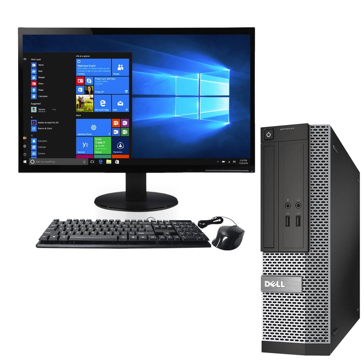
3.1. 50 Dell desktops of core i7 Intel 3.60 connected to 24x7 1GBPS high-speed Internet connections. The Dell's Intel Core i7 Desktops are optimized for content streaming, with features like high-quality displays, advanced graphics, and fast connectivity. |
|
|
|
3.2. Sony VPL-EW246 Video Projector: The VPL-EW246 is economically designed with a compact body filled with energy and cost saving features. In addition, a variety of network functions, rich inputs and outputs are available. This model is an excellent choice for education and business. It is a compact data projector that delivers exceptional image quality with eco-conscious features. In addition, a variety of network functions such as web control, network presentation and wireless presentation from mobile device can be performed. |
|
|
3.3. AutoCAD is a tool that can be used for design and drafting activities. Since it uses the computing power of a processor, CAD drawings are faster, better and more accurate than their manually drafted counterparts. It is sophisticated CAD software that is synonymous with engineering drafting. Also it is thus useful for any domain that requires 2D and 3D designs. |
|
3.4. LibreCAD is free and open-source 2D CAD software. It’s a great alternative to AutoCAD because it shares its more popular functionalities while remaining free, making it accessible for start-ups and freelancers with a reduced budget. Its file formats are compatible with AutoCAD and, when switching from one program to the other, it can still interpret layers and blocks, making it a great option even if you’re going to be communicating with an AutoCAD user. Additionally, LibreCAD has entirely free CAM capabilities, as it actually started as a CAM project. It’s available for MacOS, Windows, and Linux, and it’s particularly popular with users from the latter given the incompatibility of other programs. |
|
|
|
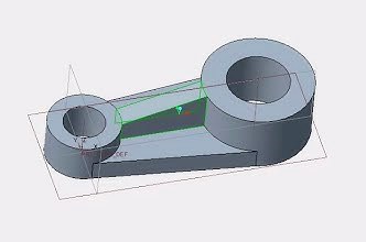
3.5. PTC Creo is a family of Computer-aided design (CAD) software supporting product design for discrete manufacturers developed by PTC. Creo runs on Microsoft Windows and provides software for 3D CAD parametric feature solid modeling, 3D direct modeling, 2D orthographic views, Finite Element Analysis and simulation, schematic design, technical illustrations, and viewing and visualization. Creo can also be paired with the MasterCAM machining based software. |
3.6. Solid Edge is a 3D CAD, parametric feature and synchronous technology solid modeling software.It runs on Microsoft Windows and provides solid modeling, assembly modeling and 2D orthographic view functionality for mechanical designers. Solid Edge is easy to learn and use, from interface to the individual tools I needed to learn a wide range of skills including complex surfacing, solid modelling, assemblies, and engineering drawings. |
|
|
|
3.7. CATIA is an acronym for Computer Aided Three-dimensional Interactive Application. It is one of the leading 3D software used by organizations in multiple industries ranging from aerospace, automobile to consumer products. It is a multi platform 3D software suite developed by Dassault Systèmes, encompassing CAD, CAM as well as CAE. |
|
3.8. Ansys Mechanical is a finite element analysis (FEA) software used to perform structural analysis using advanced solver options, including linear dynamics, nonlinearities, thermal analysis, materials, composites, hydrodynamic, explicit and more. It is uses in CFD analysis. |
|
|
|
3.9. MATLAB is an acronym for "Matrix Laboratory." It is a programming language of the fourth generation. It is a multi-paradigm, MATLAB. Therefore, it can be used with a variety of programming paradigms, including functional, Visual, and Object-Oriented. |
|
4. Suggestive List of Experiments |
|
|
Basic 2D Drafting Exercises: Basic Geometrical Shapes Orthographic Projections Dimensioning and Scaling Sectional Views Auxiliary Views Geometric Construction Intermediate 2D Drafting Exercises: Piping and Bolt Connections Machine Part Drawing (e.g., Shaft, Pulley, or Gear) Assembly Drawing Detailing with Tolerances Threads and Fasteners Advanced 2D Drafting Exercises: Advanced Assembly Drawing (e.g., Bearings, Gears, and Shafts) Welding Symbols and Weldments Cam and Follower Mechanism Complex Gear Mechanism (e.g., Spur Gears or Bevel Gears) Tolerances for Fit (Interference, Transition, and Clearance) |
3D Modeling Exercises: Basic 3D Shapes (Solid Modeling) Part Modeling (e.g., Bracket or Flange Assembly Modeling (e.g., Simple Gearbox) Complex Part Modeling (e.g., Valve Body or Turbine Blade) Simulation and Analysis
Advanced 3D Modeling and Rendering Exercises: Surface Modeling (e.g., Car Body or Turbine Blade) Render and Visualize a Product Animation of Assembly Motion Design Optimization and Topology
Additional Exercises (Specialized Areas): Sheet Metal Design Casting or Injection Moulding Technical Illustration and Exploded Views |
|
5. Suggested Books: |
6. References: |
|
L. Mathur, A Textbook of Machine Drawing, Publisher: Jain Brothers. K. R. Gopal Krishna, Machine Drawing, Subhas Pulishers, Bangalore. P. Kumar, Basic Machanical Engineering, Pearson Education India. K. L. Narayana, Machine Drawing, New Age Internationla Publishers. K. C. John, Textbook of Machine Drawing, PHI N. D. Butt, Machine Drawing, Charotar Publication, Anand. Sidheshwar, Machine Drawing, Tata McGraw Hill L. K. Narayan and P. Kanaich, Production Drawing, New Age International Publication.
|
Code of Practice for General Engineering-IS Code SP 46 (1988) – Engineering Drawing Practice for School and College.
Online Resources: https://www.cadblocksfree.com/ https://www.cadlearning.com/ |
|
FACULTY COORDINATOR: Mr. Mukul Sharma LAB INCHARGE: Mr. Mukul Sharma |
LAB CO-INCHARGE: Ms. Anushree PLACE: Room#10, Ground Floor, CSED@NIELIT |


