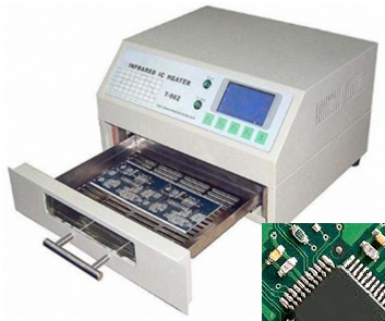
Printed Circuit Board Laboratory

Objectives:

Printed Circuit Board laboratory caters to the need of Electronic Designer. It brings out the importance of quality and reliability to Electronic Manufacturing Industries. The Printed Circuit Board are designed by considering DFM (Design for Manufacturing)/ DFA(Design for Assembly) and DFT (Design for Testing). Students are getting real world experience in PCB design and Manufacturing processes involved in Electronic Manufacturing and assembly Techniques.

Main Equipments Available

DRY FILM LAMINATOR:

Dry film process is recommended for image transfer in Printed Circuit Board fabrication process. Dry Film Laminator is needed to stick the dry film onto the PCB. The laminator removes  the protectivepolyethylene film from the dry film during lamination.The photopolymerization characteristic and the convenience of dry film photo resist make it useful for image transfer. Dry film normally gives a best  result  in fabrication of PCBs.After laminating board with photosensitive  dry film ,film master is exposed with UV light source and developed to get required image .

STENCIL PRINTER:

Stencil printer is use to deposit solder paste on the Printed Circuit Boards (PCB’s). The laser etched screen allows to dispense a set amount of solder paste required for soldering the component. One of the most important parts of the surface mount assembly process is the application of solder paste to the printed circuit board (PCB).  The aim of this process is to accurately deposit the correct amount onto each of the pads to be soldered.This is achieved by screen-printing the solder paste through a stencil printing.  


.
.

PICK AND PLACE MACHINE:SMT (surface mount technology) component placement systems, commonly called pick-and-place machines or P&Ps, are manual assisted or robotic machines which are used to place surface-mount devices (SMDs) onto a printed circuit board (PCB).

REFLOW OVEN:

Reflow soldering is a process in which a solder paste (a sticky mixture of powdered solder and flux) is used to temporarily attach one or several electrical components to their contact pads, after which the entire assembly is subjected to controlled heat, which melts the solder, permanently connecting the joint.The goal of the reflow process is to melt the solder and heat the adjoining surfaces, without overheating and damaging the electrical components. In the conventional reflow soldering process, there are usually four stages, called "zones", each having a distinct thermal profile: preheatthermal soak (often shortened to just soak), reflow, and cooling.


English